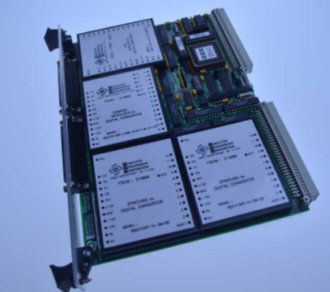
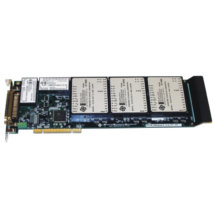
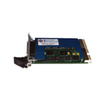
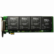
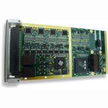
The “VB Series” product lines contains VME compatible synchro/resolver converters and absolute encoder systems. These particular cards are ideal for any rotary motion and related process, control, or simulator type application with any VME compatible system.
The VB Series provide up to eight channels of resolver or synchro conversion on a single width, standard 6U height VME card.
The VBE Series Resolver/Encoder systems feature up to 6 axis of shaft angle position encoding with a choice of single or multiturn resolvers used as the sensor inputs.
CCC’s full line of “Industry Standard” Synchro/Resolver converters, and Absolute Encoder products, are used to populate standard multifunction VME decoder cards. Differing converters may be mixed to minimize real estate for a particular application.
Both industrial and military grade (extended) temperature range versions are available, with forced air or conduction cooled models having thermal layers and expansion wedge style card locks. Accuracy applies over the operating temperature range, and 883 level B/38510 parts/processing is available on all units.
Transformer isolation is offered for all inputs and outputs, eliminating concerns for ground loops, differing potentials and high voltage field transients affecting the card itself and the VME Bus backplane.
All input cards feature Built-In Fault Detect, Self-Test command angle is optioned, and models with True Wrap Around Test (VBT’s).
Maximum versatility has been employed on all “VB” products to assure universal compatibility in addressing, timing, system, and microcomputer independence.
All VB Series converter cards are configured as A24:D16 DTB Slaves. They will respond to address modifier codes “3D” or 39 for standard addressing, and “2D” or “29” when selected for short I/O type addressing.
The VME interface is a very straightforward register based design; simply address the channel and read or write the data.
Status registers are used to provide card configuration data, and on a per channel basis, to provide channel config. and fault status.
The high speed register based interface allows these cards to operate reliably in any software environment, with uninhibited Real-Time performance.
Buffered latches are provided on all data lines to assure stable read and write cycles as commanded by the host. Address and control lines feature single point terminations to minimize any loading of the backplane. All signal output converters are provided with inherent read-back ability.
No external Power Supplies are required, every card is available as powered with standard + 12 an +5V VME Bus standard supplies. Power source jumpers are provided to select the +12VDC power input source, via the external connector port, or the VME BUS P1 backplane. CCC’s VB cards include two 25 pin polarized “D” style subminiature connectors on the front panel for all external I/O, and/or the P2 connector I/O is available as an option.
The availability of Self-Test Command Angle options (-WS), and True Wrap-Around loop back-test boards (VBT and VBDT Series), allow the user to configure automatic self test and simulation type programs at any level.
Because the VB Series uses proven, and reliable “whole” converter products, coupled with the use of leading edge LSI interface technology, the VB Series cards offer quick availability, competitive pricing and the best density verses performance ratio available in the marketplace.
The VB S/R series are 1-4 channel continuously tracking synchro or resolver to VME card converters, employing a type 2 ratiometric conversion loop for high speed/ high performance applications. They will accept any of 4 individual, or paired 3-wire synchro or 4-wire resolver inputs over a frequency range of 50 to 10KHZ., and convert them simultaneously into 10-16 bit words of natural binary data. Data is addressable in a single word 16 bit format over the VME backplane.
Data made available to the bus is continuously updated (tracking) without interruption; output data is stable, accurate, and always fresh up to the maximum tracking rate of the converter. When address and control variables are set, all data bits are latched simultaneously into separate buffered registers to prevent false reads.
Isolation
No external transformers, modules or signal conditioning is required. The synchro/resolver converters used feature internal solid-state or transformer Scott T’s that accept direct field voltage inputs.
Transformer isolated units are completely isolated from each other and the backplane for all the reference and signal lines. This completely isolates the card and effectively the whole computer from all field wiring, eliminating concerns over troublesome ground loops, differing potentials, ground interjected spikes, or ghostly field noise that so frequently takes down entire systems.
Multispeed/Multiturn
The VBR Hardware inherently supports four channels of discreet S-D/R-D conversion, two channels of multispeed/multiturn S-D/R-D conversion, or a combination of both.
The Firmware supports simultaneous two channel store-to-read configuration required to properly interrogate multispeed/multiturn resolvers and synchro’s. Furthermore, precombined converters can be supplied as an option.
Bus Powered
Power required is +15 and +5VDC as standard; +12VDC is optioned, and the source for the +12 or +15V input is strap selectable for power sourcing via the backplane or externally powered via the I/O connector.

