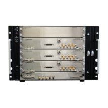
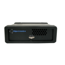
The EX7300 (3U) – EX7600 (6U) are a line of complete enclosures that include a 150 W power supply, the EX7000-OEM LXI digital interface and driver card, fans for cooling, and a removable tray for mounting components and cables. These units are intended for customers who wish to develop, build, and support their own RF/Microwave, optical, or power interface subassemblies while minimizing the time spent developing a software and communications interface.
FLEXIBLE CONTROL BASED ON THE EX7000-OEM
Consistent with all products within the EX7000 family, the EX7300 – EX7600 enclosures leverage off the powerful command and control options of the EX7000-OEM (see EX7000-OEM). A list of components used in the design can be built through VTI’s broadband design wizard. This list can be uploaded to the custom enclosure and a JAVA-driven graphical configuration utility is then employed to programmatically emulate the schematic, while providing a “path-level” IVI driver interface and an intuitive, soft front panel for easy debug and control.
EFFICIENT DESIGN FACILITATES EASY DEVELOPMENT
A removable tray allows the enclosure to be easily “punched” for the mounting of components and cables. Additionally, 3D drawings of the cable tray are available for users who wish to mechanically design the custom tray and have either VTI Instruments or a machine shop fabricate the subassembly. The component tray also allows I/O connectors to be mounted on either the rear or front panels providing the flexibility to keep external cable lengths to the enclosure at a minimum, regardless of the connector orientation of the other system assets.